
Machining cycle
Grooving on a CNC lathe
Cutting grooves of a given width and depth
A clickable cycle form: tap any field to see what it does.
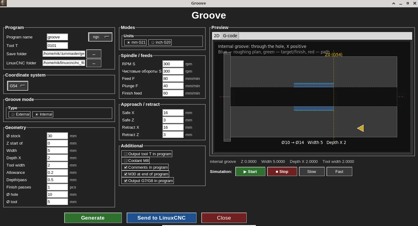
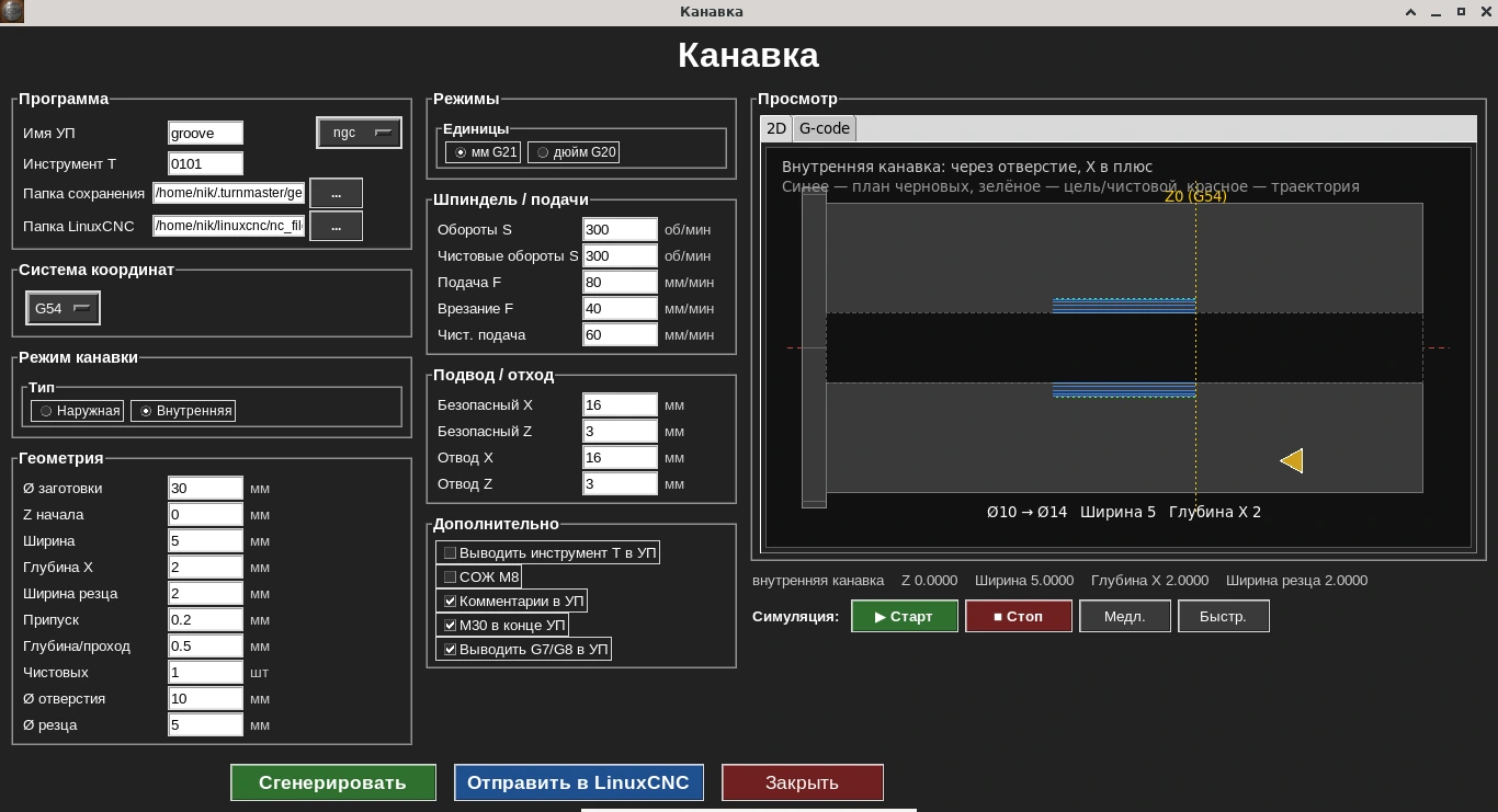
Cycle form: internal groove inside a bore shown — bore diameter, groove width and depth, live 2D toolpath simulator on the right.
The groove cycle cuts a slot at the given diameter over one or several passes, accounting for the tool width and the required groove width.
Who needs this cycle
Needed for retaining-ring grooves, seal grooves, thread relief, and other functional grooves.
Key form parameters
- •Diameter where the groove sits
- •Groove width
- •Groove depth
- •Tool width
- •Feed rate
G-code example
Real output of the Groove cycle for an internal groove: in a Ø10 mm bore (Ø30 blank) a groove 5 mm wide — from Z−3 to Z−8 — and 2 mm deep per side, to Ø14, is cut. Tool width 2 mm, tool Ø 5 mm, depth per pass 0.5 mm, 0.2 mm allowance, plunge 40 mm/min, finishing feed 60 mm/min, 300 rpm. The code lines were not edited by hand.
As in boring, X in the code is the tool centre: the edge is further from the axis by the tool radius (2.5 mm). So the final X4.5 puts the edge at R7, i.e. Ø14. Radius mode G8.
The algorithm is written right in the header: the groove is cut in X layers — on each layer the tool plunges across the full groove width, then moves to the next layer.
groove.ngc · 100 lines — Show the full program
%
(Turn G-code)
(Groove: internal: centre at X0, move in Z, plunge in X+, layer by layer)
(Algorithm: X layer -> plunges across the full groove width -> next layer)
(Stock Ø: 30.0000)
(Bore Ø: 10.0000)
(Tool Ø: 5.0000)
(Start Z: -3.0000)
(Groove width: 5.0000)
(Tool width: 2.0000)
(Depth X: 2.0000)
(Allowance: 0.2000)
(Depth/pass: 0.5000)
(Plunge Z: -3.0000, -5.0000, -6.0000)
(Turning feed F: 80.0000)
(Plunge feed F: 40.0000)
(Finish feed: 60.0000)

G21 G18 G90 G8 G40 G80 G94
G54

G97 S300 M3
G0 Z3.0000
G0 X16.0000
G0 X0.0000

(Roughing layer 1 of 4)
(Layer X3.0000: plunges along Z, plunge F40.0000)
(  Plunge 1 of 3: Z-3.0000)
G0 Z-3.0000
G1 X3.0000 F40.0000
G0 X0.0000
(  Plunge 2 of 3: Z-5.0000)
G0 Z-5.0000
G1 X3.0000 F40.0000
G0 X0.0000
(  Plunge 3 of 3: Z-6.0000)
G0 Z-6.0000
G1 X3.0000 F40.0000
G0 X0.0000

(Roughing layer 2 of 4)
(Layer X3.5000: plunges along Z, plunge F40.0000)
(  Plunge 1 of 3: Z-3.0000)
G0 Z-3.0000
G1 X3.5000 F40.0000
G0 X0.0000
(  Plunge 2 of 3: Z-5.0000)
G0 Z-5.0000
G1 X3.5000 F40.0000
G0 X0.0000
(  Plunge 3 of 3: Z-6.0000)
G0 Z-6.0000
G1 X3.5000 F40.0000
G0 X0.0000

(Roughing layer 3 of 4)
(Layer X4.0000: plunges along Z, plunge F40.0000)
(  Plunge 1 of 3: Z-3.0000)
G0 Z-3.0000
G1 X4.0000 F40.0000
G0 X0.0000
(  Plunge 2 of 3: Z-5.0000)
G0 Z-5.0000
G1 X4.0000 F40.0000
G0 X0.0000
(  Plunge 3 of 3: Z-6.0000)
G0 Z-6.0000
G1 X4.0000 F40.0000
G0 X0.0000

(Roughing layer 4 of 4)
(Layer X4.3000: plunges along Z, plunge F40.0000)
(  Plunge 1 of 3: Z-3.0000)
G0 Z-3.0000
G1 X4.3000 F40.0000
G0 X0.0000
(  Plunge 2 of 3: Z-5.0000)
G0 Z-5.0000
G1 X4.3000 F40.0000
G0 X0.0000
(  Plunge 3 of 3: Z-6.0000)
G0 Z-6.0000
G1 X4.3000 F40.0000
G0 X0.0000

(Finishing spindle speed)
S300
(Finish pass 1 of 1)
(Finish bottom/walls: plunge at plunge F, Z move at finish F)
G0 Z-3.0000
G1 X4.5000 F40.0000
G1 Z-6.0000 F60.0000
G0 X0.0000

G0 Z3.0000
G0 X16.0000
M5
M30
%
Line-by-line breakdown
G21 G18 G90 G8 G40 G80 G94- Start: millimetres, XZ plane, absolute coordinates, radius mode for X (G8), cancel compensation and canned cycles, feed in mm/min.
G97 S300 M3 / G0 Z3.0000 / G0 X16.0000 / G0 X0.0000- 300 rpm, approach in front of the face and move to the part axis (X0) — from here the tool enters the bore.
G0 Z-3.0000 → G1 X3.0000 F40.0000 → G0 X0.0000- Plunge: move to Z, plunge in X at 40 mm/min to X3.0 (edge at R5.5 — 0.5 mm into the bore wall) and rapid back to the axis.
( Plunge 2 of 3: Z-5.0000) / ( Plunge 3 of 3: Z-6.0000)- Three plunges at Z−3, Z−5 and Z−6 with a 2 mm wide tool cover the full groove width — Z−3…−8.
(Roughing layer 2 of 4) … (Roughing layer 4 of 4)- Layers step 0.5 mm: X3.5, X4.0, and the last one X4.3, leaving 0.2 mm for the finishing pass.
G0 Z-3.0000 / G1 X4.5000 F40.0000 / G1 Z-6.0000 F60.0000- Finishing pass: plunge to full depth X4.5 (Ø14) and a pass along the groove bottom in Z at the 60 mm/min finishing feed.
G0 Z3.0000 / G0 X16.0000 / M5 / M30- Exit the bore, retract, spindle stop and program end.
Comments in this program were translated from Russian; the G-code itself is unchanged.
What the codes in this program mean (G0, G1, G8, G97, M3, M5) — G- and M-code reference for lathes.
Frequently asked questions
How does the cycle account for tool width?
Tool width is a separate parameter — the cycle works out the number of passes and their offset so the groove comes out at the exact required width, even if the tool is narrower.
Can a groove be cut over several passes?
Yes, if the groove's width or depth requires more than one pass of the tool, the cycle distributes them automatically.
What are these grooves typically used for?
Retaining-ring grooves, seal grooves, thread relief, and other functional grooves.
Does the cycle work for internal grooves inside a bore?
Yes, the example shown is exactly that — an internal groove inside a bore; the parameters are set the same way as for an external groove.