
Machining cycle
Taper turning on a CNC lathe
External and internal conical machining
A clickable cycle form: tap any field to see what it does.
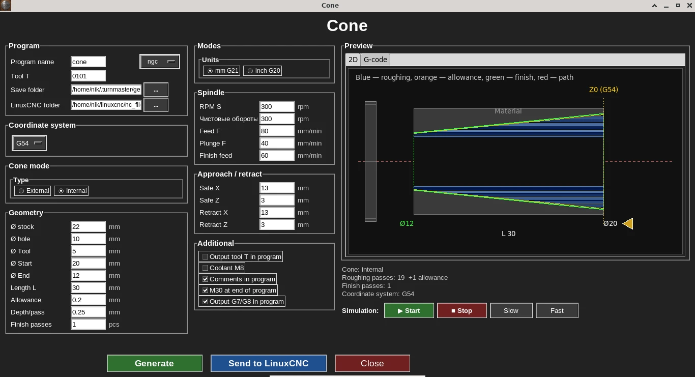
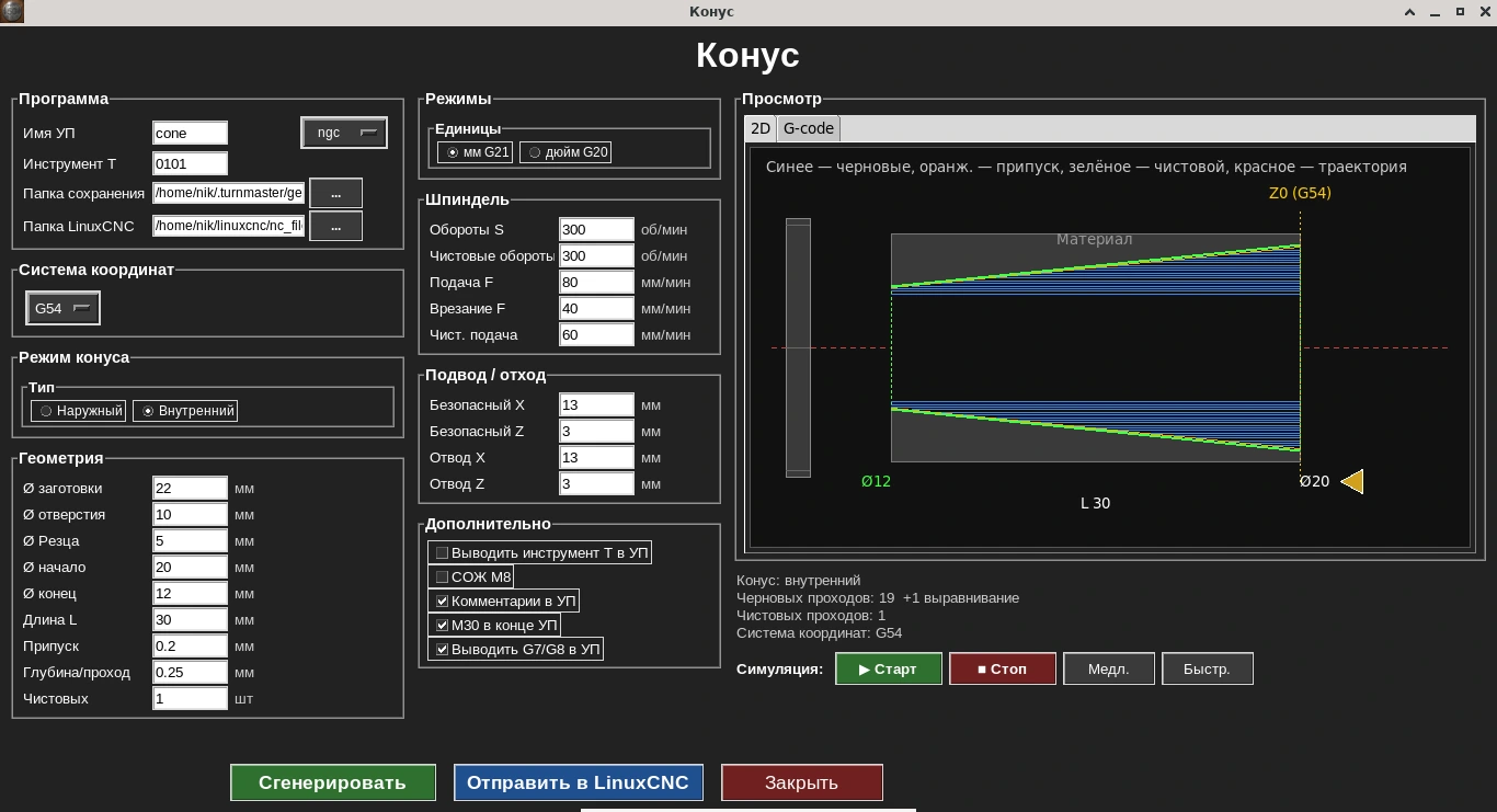
Cycle form: internal cone shown — start and end diameters set the angle, live 2D toolpath simulator on the right.
The taper cycle removes material along a conical path between two given diameters over a given length, supporting both external and internal machining.
Who needs this cycle
Needed for parts with conical surfaces — centers, tapered fits, transition sections on shafts.
Key form parameters
- •Start and end diameter
- •Length of the taper
- •External/internal machining
- •Feed rate
- •Spindle speed
G-code example
Real output of the Taper cycle for an external taper: a Ø22 mm blank becomes a Ø20 → Ø12 taper over 30 mm. Depth per pass 0.25 mm, finishing allowance 0.2 mm, plunge feed 40 mm/min, cutting feed 80 mm/min, finishing feed 60 mm/min; roughing at 300 rpm, finishing at 555 rpm. The code lines were not edited by hand.
Radius mode G8: X in the code is half the diameter. Ø20 is written as X10, Ø12 as X6, the Ø22 blank as X11.
Roughing is done in cylindrical steps: each pass removes 0.25 mm per side, and its start in Z shifts along the taper so the future tapered surface is never gouged. Then one pass along the profile with allowance removes the steps, and the finishing pass brings the taper to size.
taper.ngc · 177 lines — Show the full program
%
(Turn G-code)
(External taper)
(D start: 20.0000)
(D end: 12.0000)
(Stock Ø: 22.0000)
(Bore Ø: 10.0000)
(Length: 30.0000)
(Finish allowance: 0.2000)
(Depth per pass: 0.2500)
(Cutting F: 80.0000)
(Plunge F: 40.0000)
(Final X1: 10.0000)
(Final X2: 6.0000)

G21 G18 G90 G8 G40 G80 G94
G54

G97 S300 M3
G0 Z3.0000
G0 X13.0000

G0 Z-0.0000

(Roughing pass 1 of 20)
(Roughing as a cylinder at X10.7500; profile with allowance X10.2000->6.2000)
G1 X10.7500 F40.0000
G1 Z-30.0000 F80.0000
G0 X13.0000
G0 Z-0.0000

(Roughing pass 2 of 20)
(Roughing as a cylinder at X10.5000; profile with allowance X10.2000->6.2000)
G1 X10.5000 F40.0000
G1 Z-30.0000 F80.0000
G0 X13.0000
G0 Z-0.0000

(Roughing pass 3 of 20)
(Roughing as a cylinder at X10.2500; profile with allowance X10.2000->6.2000)
G1 X10.2500 F40.0000
G1 Z-30.0000 F80.0000
G0 X13.0000
G0 Z-1.5000

(Roughing pass 4 of 20)
(Roughing as a cylinder at X10.0000; profile with allowance X10.2000->6.2000)
G1 X10.0000 F40.0000
G1 Z-30.0000 F80.0000
G0 X13.0000
G0 Z-3.3750

(Roughing pass 5 of 20)
(Roughing as a cylinder at X9.7500; profile with allowance X10.2000->6.2000)
G1 X9.7500 F40.0000
G1 Z-30.0000 F80.0000
G0 X13.0000
G0 Z-5.2500

(Roughing pass 6 of 20)
(Roughing as a cylinder at X9.5000; profile with allowance X10.2000->6.2000)
G1 X9.5000 F40.0000
G1 Z-30.0000 F80.0000
G0 X13.0000
G0 Z-7.1250

(Roughing pass 7 of 20)
(Roughing as a cylinder at X9.2500; profile with allowance X10.2000->6.2000)
G1 X9.2500 F40.0000
G1 Z-30.0000 F80.0000
G0 X13.0000
G0 Z-9.0000

(Roughing pass 8 of 20)
(Roughing as a cylinder at X9.0000; profile with allowance X10.2000->6.2000)
G1 X9.0000 F40.0000
G1 Z-30.0000 F80.0000
G0 X13.0000
G0 Z-10.8750

(Roughing pass 9 of 20)
(Roughing as a cylinder at X8.7500; profile with allowance X10.2000->6.2000)
G1 X8.7500 F40.0000
G1 Z-30.0000 F80.0000
G0 X13.0000
G0 Z-12.7500

(Roughing pass 10 of 20)
(Roughing as a cylinder at X8.5000; profile with allowance X10.2000->6.2000)
G1 X8.5000 F40.0000
G1 Z-30.0000 F80.0000
G0 X13.0000
G0 Z-14.6250

(Roughing pass 11 of 20)
(Roughing as a cylinder at X8.2500; profile with allowance X10.2000->6.2000)
G1 X8.2500 F40.0000
G1 Z-30.0000 F80.0000
G0 X13.0000
G0 Z-16.5000

(Roughing pass 12 of 20)
(Roughing as a cylinder at X8.0000; profile with allowance X10.2000->6.2000)
G1 X8.0000 F40.0000
G1 Z-30.0000 F80.0000
G0 X13.0000
G0 Z-18.3750

(Roughing pass 13 of 20)
(Roughing as a cylinder at X7.7500; profile with allowance X10.2000->6.2000)
G1 X7.7500 F40.0000
G1 Z-30.0000 F80.0000
G0 X13.0000
G0 Z-20.2500

(Roughing pass 14 of 20)
(Roughing as a cylinder at X7.5000; profile with allowance X10.2000->6.2000)
G1 X7.5000 F40.0000
G1 Z-30.0000 F80.0000
G0 X13.0000
G0 Z-22.1250

(Roughing pass 15 of 20)
(Roughing as a cylinder at X7.2500; profile with allowance X10.2000->6.2000)
G1 X7.2500 F40.0000
G1 Z-30.0000 F80.0000
G0 X13.0000
G0 Z-24.0000

(Roughing pass 16 of 20)
(Roughing as a cylinder at X7.0000; profile with allowance X10.2000->6.2000)
G1 X7.0000 F40.0000
G1 Z-30.0000 F80.0000
G0 X13.0000
G0 Z-25.8750

(Roughing pass 17 of 20)
(Roughing as a cylinder at X6.7500; profile with allowance X10.2000->6.2000)
G1 X6.7500 F40.0000
G1 Z-30.0000 F80.0000
G0 X13.0000
G0 Z-27.7500

(Roughing pass 18 of 20)
(Roughing as a cylinder at X6.5000; profile with allowance X10.2000->6.2000)
G1 X6.5000 F40.0000
G1 Z-30.0000 F80.0000
G0 X13.0000
G0 Z-29.6250

(Roughing pass 19 of 20)
(Roughing as a cylinder at X6.2500; profile with allowance X10.2000->6.2000)
G1 X6.2500 F40.0000
G1 Z-30.0000 F80.0000
G0 X13.0000
G0 Z0.0000

(Taper cleanup to the allowance)
(Profile X10.2000->6.2000)
G1 X10.2000 F40.0000
G1 X6.2000 Z-30.0000 F80.0000
G0 X13.0000
G0 Z0.0000

(Finishing spindle speed)
S555
(Finish pass 1 of 1)
(Profile X10.0000->6.0000)
G1 X10.0000 F40.0000
G1 X6.0000 Z-30.0000 F60.0000
G0 X13.0000
G0 Z3.0000

G0 Z3.0000
M5
M30
%
Line-by-line breakdown
G21 G18 G90 G8 G40 G80 G94- Start: millimetres, XZ plane, absolute coordinates, radius mode for X (G8), cancel compensation and canned cycles, feed in mm/min.
G97 S300 M3 / G0 Z3.0000 / G0 X13.0000- 300 rpm and a rapid to 3 mm in front of the face at X13 (Ø26) — above the Ø22 blank.
G1 X10.7500 F40.0000 → G1 Z-30.0000 F80.0000- First roughing pass: plunge in X at 40 mm/min to X10.75 (Ø21.5), then turn a cylinder to Z−30 at 80 mm/min.
G0 X13.0000 / G0 Z-1.5000- Retract and move to the start of the next pass. From the fourth pass the Z start shifts (Z−1.5, Z−3.375, Z−5.25 …): the X10.0 cylinder can only be cut where the taper with allowance is already below that radius.
G1 X10.2000 F40.0000 / G1 X6.2000 Z-30.0000 F80.0000- “Taper cleanup to the allowance”: one pass along the sloped profile with a 0.2 mm allowance (X10.2 → X6.2) removes the ridges left between the cylinders.
S555 / G1 X10.0000 F40.0000 / G1 X6.0000 Z-30.0000 F60.0000- Finishing pass along the final Ø20 → Ø12 profile at 555 rpm and 60 mm/min. Simultaneous X and Z motion produces a smooth tapered surface.
M5 / M30- Spindle stop and program end.
Comments in this program were translated from Russian; the G-code itself is unchanged. The “Bore Ø” header line belongs to the internal taper mode: for an external taper it is printed along with the other form fields but does not affect this toolpath.
What the codes in this program mean (G0, G1, G8, G97, M3, M5) — G- and M-code reference for lathes.
Frequently asked questions
How is taper different from turning?
Turning machines a surface at a constant diameter, while taper changes the diameter linearly from a start to an end value over a given length, forming a conical surface.
Can I machine both external and internal tapers?
Yes, the cycle supports both — external and internal conical machining.
What parts is this cycle for?
Parts with conical surfaces — centers, tapered fits, transition sections on shafts.
Can I preview the toolpath before generating the G-code?
Yes, the cycle form shows a live 2D toolpath simulator.