
Machining cycle
Archimedean spiral on the part face
A face spiral thread/groove following the Archimedean spiral
A clickable cycle form: tap any field to see what it does.
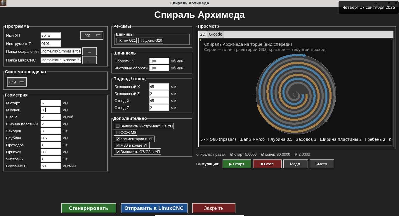
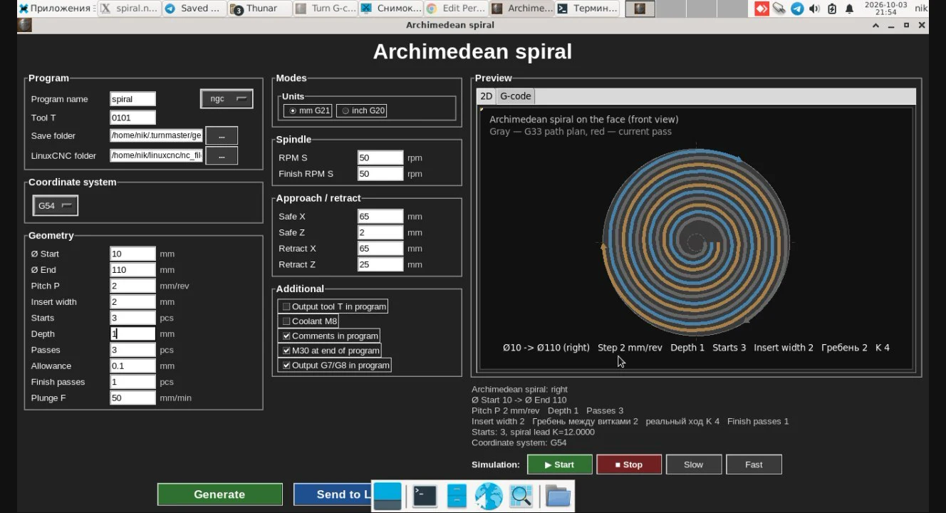
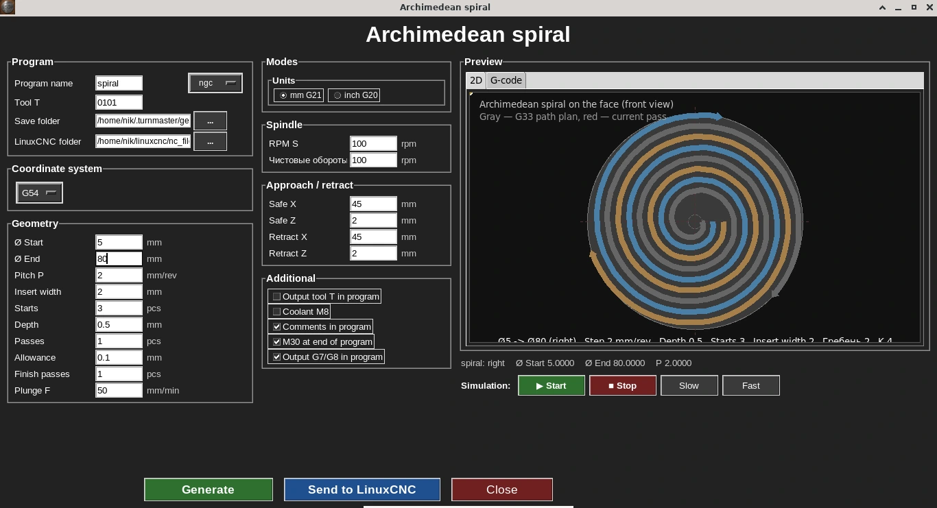
The cycle form: start/end diameters, pitch, insert width and number of starts, with a live 2D path simulator on the right.
The exact parameters used for the cut in the video below: Ø10 → Ø110 mm, 3 starts, 2 mm insert + 2 mm land (4 mm per turn, spiral lead 12 mm), 1 mm deep in 3 passes + 1 finishing pass, 50 RPM, right-hand spiral.
The Archimedean spiral cycle cuts a groove or thread into the face of the workpiece, following a spiral with a uniform pitch from the center outward or the reverse.
The cycle runs on a spindle-synchronized threading move (G32/G33) — the same principle as regular threading, just radial along X instead of along Z, and only on the part's face. Because of that, the generated program only works on machines where the controller and spindle drive track rotation through an encoder (a spindle position sensor): without one, feed can't be synchronized to rotation, and the machine can't run this G-code correctly.
Archimedean spiral: a real cut
Who needs this cycle
Needed for non-standard face spiral profiles — for example, spiral grooves or a thread cut into the face of a part.
Key form parameters
- •Start and end spiral radius
- •Spiral pitch
- •Groove/thread depth
- •Feed rate
G-code example
Real output of the Archimedean spiral cycle: a three-start spiral groove on the face, from Ø5 to Ø80, 1 mm deep. 2 mm insert, 4 depth passes (0.3 / 0.6 / 0.9 / 1.0 mm), plunge 50 mm/min, 100 rpm. Motion is G33 with K. The code lines were not edited by hand.
Radius mode G8: Ø5 is X2.5, Ø80 is X40. The tool moves only in X, from the centre outwards, while the spindle turns in sync — that is what cuts a spiral into the face.
In the code, neighbouring turns are 4 mm apart on radius: the three starts begin at X2.5, X6.5 and X10.5, and the spiral lead per revolution is K12 — 3 starts × 4 mm. With a 2 mm insert this gives a 2 mm wide groove and a 2 mm land between turns.
archimedean-spiral.ngc · 111 lines — Show the full program
%
(Turn G-code)
(Archimedean spiral on the face)
(Thread motion: G33 K)
(Direction: right-hand)
(Starts: 3)
(D start: 5.0000)
(D end: 80.0000)
(Pitch P: 2.0000)
(Insert width: 2.0000)
(Spiral lead per revolution, K in G-code: 12.0000)
(Depth: 1.0000)
(Plunge feed F: 50.0000)

G21 G18 G90 G8 G40 G80 G94
G54

G97 S100 M3
G0 Z2.0000
G0 X45.0000

(Pass 1 of 4, start 1 of 3, Z-0.3000)
G0 X2.5000
G1 Z-0.3000 F50.0000
G33 X40.0000 K12.0000
G0 Z2.0000
G0 X45.0000

(Pass 1 of 4, start 2 of 3, Z-0.3000)
G0 X6.5000
G1 Z-0.3000 F50.0000
G33 X40.0000 K12.0000
G0 Z2.0000
G0 X45.0000

(Pass 1 of 4, start 3 of 3, Z-0.3000)
G0 X10.5000
G1 Z-0.3000 F50.0000
G33 X40.0000 K12.0000
G0 Z2.0000
G0 X45.0000

(Pass 2 of 4, start 1 of 3, Z-0.6000)
G0 X2.5000
G1 Z-0.6000 F50.0000
G33 X40.0000 K12.0000
G0 Z2.0000
G0 X45.0000

(Pass 2 of 4, start 2 of 3, Z-0.6000)
G0 X6.5000
G1 Z-0.6000 F50.0000
G33 X40.0000 K12.0000
G0 Z2.0000
G0 X45.0000

(Pass 2 of 4, start 3 of 3, Z-0.6000)
G0 X10.5000
G1 Z-0.6000 F50.0000
G33 X40.0000 K12.0000
G0 Z2.0000
G0 X45.0000

(Pass 3 of 4, start 1 of 3, Z-0.9000)
G0 X2.5000
G1 Z-0.9000 F50.0000
G33 X40.0000 K12.0000
G0 Z2.0000
G0 X45.0000

(Pass 3 of 4, start 2 of 3, Z-0.9000)
G0 X6.5000
G1 Z-0.9000 F50.0000
G33 X40.0000 K12.0000
G0 Z2.0000
G0 X45.0000

(Pass 3 of 4, start 3 of 3, Z-0.9000)
G0 X10.5000
G1 Z-0.9000 F50.0000
G33 X40.0000 K12.0000
G0 Z2.0000
G0 X45.0000

(Finishing spindle speed)
S100
(Pass 4 of 4, start 1 of 3, Z-1.0000)
G0 X2.5000
G1 Z-1.0000 F50.0000
G33 X40.0000 K12.0000
G0 Z2.0000
G0 X45.0000

(Pass 4 of 4, start 2 of 3, Z-1.0000)
G0 X6.5000
G1 Z-1.0000 F50.0000
G33 X40.0000 K12.0000
G0 Z2.0000
G0 X45.0000

(Pass 4 of 4, start 3 of 3, Z-1.0000)
G0 X10.5000
G1 Z-1.0000 F50.0000
G33 X40.0000 K12.0000
G0 Z2.0000
G0 X45.0000

G0 X45.0000
M5
M30
%
Line-by-line breakdown
G21 G18 G90 G8 G40 G80 G94- Start: millimetres, XZ plane, absolute coordinates, radius mode for X (G8), cancel compensation and canned cycles, feed in mm/min.
G97 S100 M3 / G0 Z2.0000 / G0 X45.0000- Constant 100 rpm, approach to 2 mm in front of the face and past the part edge (X45).
G0 X2.5000 → G1 Z-0.3000 F50.0000- Start 1: move to the starting radius X2.5 (Ø5) and plunge 0.3 mm into the face at 50 mm/min.
G33 X40.0000 K12.0000- Spiral move: the tool travels in X to X40 (Ø80) in sync with the spindle; K12 is the spiral lead per revolution (as labelled in the program header).
G0 Z2.0000 / G0 X45.0000- Exit the groove in Z and retract past the edge before the next start.
G0 X6.5000 / G0 X10.5000- Starts 2 and 3 begin offset by 4 mm on radius (X6.5 and X10.5) — the three spirals sit between each other at equal intervals.
(Pass 2 of 4, start 1 of 3, Z-0.6000) … (Pass 4 of 4, start 3 of 3, Z-1.0000)- At each depth all three starts are cut, then the tool goes deeper: Z−0.6, Z−0.9 and the final Z−1.0.
M5 / M30- Spindle stop and program end.
Comments in this program were translated from Russian; the G-code itself is unchanged.
What the codes in this program mean (G0, G1, G33, G8, M3, M5) — G- and M-code reference for lathes.
More on this topic: Archimedean spiral on a face: cutting a spiral groove on a CNC lathe.
Frequently asked questions
What principle does this cycle work on?
A spindle-synchronized threading move (G32/G33) — the same one used for regular threading, just running radially along X instead of along Z, and only on the part's face.
Will this work on any machine?
No — the generated program only runs correctly on machines where the controller and spindle drive track rotation through an encoder (a spindle position sensor). Without one, feed can't be synchronized to rotation.
Which direction can the spiral go?
From the center outward or from the edge inward — the direction is set by the start and end spiral radius. The same choice sets the hand: swap the start and end diameters and, with the same spindle direction, you get a left-hand spiral instead of a right-hand one.
What is this cycle for?
Non-standard face spiral profiles — for example, spiral grooves or a thread cut into the face of a part.