
Machining cycle
Parting off on a CNC lathe
Parting off the finished part from the stock
A clickable cycle form: tap any field to see what it does.
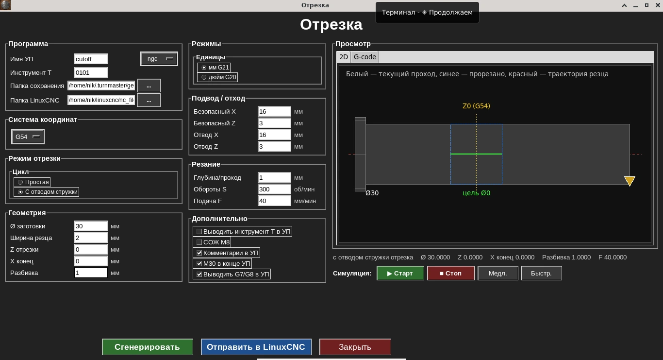
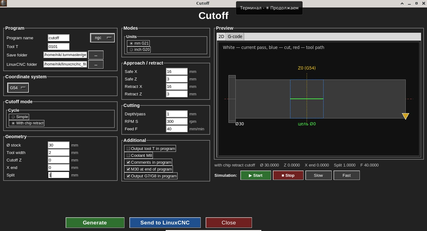
The cycle form: cutoff with chip retract shown — stock diameter, tool width, X end and split, with a live 2D path simulator on the right.
The cutoff cycle moves the parting tool toward the workpiece axis at the given position, with an optional edge chamfer before parting.
Who needs this cycle
Needed for the final operation — separating the finished part from bar stock.
Key form parameters
- •Workpiece diameter
- •Cutoff position
- •Parting tool width
- •Feed rate
- •Spindle speed
G-code example
Real output of the Cut-off cycle: external parting of Ø30 mm bar stock with a 2 mm wide insert, in chip-clearing mode. Depth per pass 1 mm per side, 13 passes down to X2, plunge feed 40 mm/min, 300 rpm. The code lines were not edited by hand.
It is important to understand how the Z position is set: in this cycle Z is the centre of the insert. In the example the cut-off Z is 1.0, so the 2 mm insert sits between Z0 and Z2. Where the cut lands on the real part depends on the part zero (G54) the operator sets on the machine. To part off a piece of length L from the face with the zero on the face, set the cut-off Z to −(L + 1): for example −26 for a 25 mm part — the insert edge then lands exactly at Z−25.
Radius mode G8: the Ø30 blank is X15, the safe retract is X16 (Ø32), the end point X2 is Ø4.
cutoff.ngc · 206 lines — Show the full program
%
(Turn G-code)
(External cut-off)
(Stock Ø: 30.0000)
(Tool width: 2.0000)
(Cut-off Z: 1.0000)
(End X: 2.0000)
(Widening: 1.0000)
(Mode: with chip clearing)

G21 G18 G90 G8 G40 G80 G94
G54

G97 S300 M3
G0 X16.0000
G0 Z3.0000
G0 Z1.0000

(Cut-off with chip clearing: depth/pass 1.0000, widening 1.0000)
(Pass 1 of 13: X14.0000)
G1 X14.0000 F40.0000
G0 X16.0000
(Widening: left edge, Z0.5000, X14.0000)
G0 X16.0000
G0 Z0.5000
G1 X14.0000 F40.0000
G0 X16.0000
(Widening: right edge, Z1.5000, X14.0000)
G0 X16.0000
G0 Z1.5000
G1 X14.0000 F40.0000
G0 X16.0000
G0 Z1.0000
(Pass 2 of 13: X13.0000)
G1 X13.0000 F40.0000
G0 X16.0000
(Widening: left edge, Z0.5000, X13.0000)
G0 X16.0000
G0 Z0.5000
G1 X13.0000 F40.0000
G0 X16.0000
(Widening: right edge, Z1.5000, X13.0000)
G0 X16.0000
G0 Z1.5000
G1 X13.0000 F40.0000
G0 X16.0000
G0 Z1.0000
(Pass 3 of 13: X12.0000)
G1 X12.0000 F40.0000
G0 X16.0000
(Widening: left edge, Z0.5000, X12.0000)
G0 X16.0000
G0 Z0.5000
G1 X12.0000 F40.0000
G0 X16.0000
(Widening: right edge, Z1.5000, X12.0000)
G0 X16.0000
G0 Z1.5000
G1 X12.0000 F40.0000
G0 X16.0000
G0 Z1.0000
(Pass 4 of 13: X11.0000)
G1 X11.0000 F40.0000
G0 X16.0000
(Widening: left edge, Z0.5000, X11.0000)
G0 X16.0000
G0 Z0.5000
G1 X11.0000 F40.0000
G0 X16.0000
(Widening: right edge, Z1.5000, X11.0000)
G0 X16.0000
G0 Z1.5000
G1 X11.0000 F40.0000
G0 X16.0000
G0 Z1.0000
(Pass 5 of 13: X10.0000)
G1 X10.0000 F40.0000
G0 X16.0000
(Widening: left edge, Z0.5000, X10.0000)
G0 X16.0000
G0 Z0.5000
G1 X10.0000 F40.0000
G0 X16.0000
(Widening: right edge, Z1.5000, X10.0000)
G0 X16.0000
G0 Z1.5000
G1 X10.0000 F40.0000
G0 X16.0000
G0 Z1.0000
(Pass 6 of 13: X9.0000)
G1 X9.0000 F40.0000
G0 X16.0000
(Widening: left edge, Z0.5000, X9.0000)
G0 X16.0000
G0 Z0.5000
G1 X9.0000 F40.0000
G0 X16.0000
(Widening: right edge, Z1.5000, X9.0000)
G0 X16.0000
G0 Z1.5000
G1 X9.0000 F40.0000
G0 X16.0000
G0 Z1.0000
(Pass 7 of 13: X8.0000)
G1 X8.0000 F40.0000
G0 X16.0000
(Widening: left edge, Z0.5000, X8.0000)
G0 X16.0000
G0 Z0.5000
G1 X8.0000 F40.0000
G0 X16.0000
(Widening: right edge, Z1.5000, X8.0000)
G0 X16.0000
G0 Z1.5000
G1 X8.0000 F40.0000
G0 X16.0000
G0 Z1.0000
(Pass 8 of 13: X7.0000)
G1 X7.0000 F40.0000
G0 X16.0000
(Widening: left edge, Z0.5000, X7.0000)
G0 X16.0000
G0 Z0.5000
G1 X7.0000 F40.0000
G0 X16.0000
(Widening: right edge, Z1.5000, X7.0000)
G0 X16.0000
G0 Z1.5000
G1 X7.0000 F40.0000
G0 X16.0000
G0 Z1.0000
(Pass 9 of 13: X6.0000)
G1 X6.0000 F40.0000
G0 X16.0000
(Widening: left edge, Z0.5000, X6.0000)
G0 X16.0000
G0 Z0.5000
G1 X6.0000 F40.0000
G0 X16.0000
(Widening: right edge, Z1.5000, X6.0000)
G0 X16.0000
G0 Z1.5000
G1 X6.0000 F40.0000
G0 X16.0000
G0 Z1.0000
(Pass 10 of 13: X5.0000)
G1 X5.0000 F40.0000
G0 X16.0000
(Widening: left edge, Z0.5000, X5.0000)
G0 X16.0000
G0 Z0.5000
G1 X5.0000 F40.0000
G0 X16.0000
(Widening: right edge, Z1.5000, X5.0000)
G0 X16.0000
G0 Z1.5000
G1 X5.0000 F40.0000
G0 X16.0000
G0 Z1.0000
(Pass 11 of 13: X4.0000)
G1 X4.0000 F40.0000
G0 X16.0000
(Widening: left edge, Z0.5000, X4.0000)
G0 X16.0000
G0 Z0.5000
G1 X4.0000 F40.0000
G0 X16.0000
(Widening: right edge, Z1.5000, X4.0000)
G0 X16.0000
G0 Z1.5000
G1 X4.0000 F40.0000
G0 X16.0000
G0 Z1.0000
(Pass 12 of 13: X3.0000)
G1 X3.0000 F40.0000
G0 X16.0000
(Widening: left edge, Z0.5000, X3.0000)
G0 X16.0000
G0 Z0.5000
G1 X3.0000 F40.0000
G0 X16.0000
(Widening: right edge, Z1.5000, X3.0000)
G0 X16.0000
G0 Z1.5000
G1 X3.0000 F40.0000
G0 X16.0000
G0 Z1.0000
(Pass 13 of 13: X2.0000)
G1 X2.0000 F40.0000
G0 X16.0000
(Widening: left edge, Z0.5000, X2.0000)
G0 X16.0000
G0 Z0.5000
G1 X2.0000 F40.0000
G0 X16.0000
(Widening: right edge, Z1.5000, X2.0000)
G0 X16.0000
G0 Z1.5000
G1 X2.0000 F40.0000
G0 X16.0000
G0 Z1.0000

G0 Z3.0000
M5
M30
%
Line-by-line breakdown
G21 G18 G90 G8 G40 G80 G94- Start: millimetres, XZ plane, absolute coordinates, radius mode for X (G8), cancel compensation and canned cycles, feed in mm/min.
G97 S300 M3 / G0 X16.0000 / G0 Z3.0000 / G0 Z1.0000- 300 rpm: first clear in X above the blank (X16), then move in Z to the cut-off position — insert centre at Z1.
G1 X14.0000 F40.0000 → G0 X16.0000- First pass: plunge at 40 mm/min to X14, then a full retract to X16 — the chip leaves the slot and the insert does not bind.
(Widening: left edge, Z0.5000, X14.0000) / (Widening: right edge, Z1.5000, X14.0000)- “Widening”: two more plunges at the same depth, shifted 0.5 mm left (Z0.5) and right (Z1.5). The slot becomes 3 mm wide for a 2 mm insert, so its sides do not rub against the walls.
G0 Z1.0000- Back to the main Z1 position before the next, deeper pass.
(Pass 2 of 13: X13.0000) … (Pass 13 of 13: X2.0000)- Each pass goes 1 mm deeper: X13, X12 … X2. The cut-off ends at X2 — a Ø4 neck, as set by the “End X” field in the form.
G0 Z3.0000 / M5 / M30- Retract, spindle stop and program end.
Comments in this program were translated from Russian; the G-code itself is unchanged.
What the codes in this program mean (G0, G1, G8, G97, M3, M5) — G- and M-code reference for lathes.
More on this topic: G96 and G97 on a CNC lathe: constant surface speed vs constant RPM.
Frequently asked questions
Can I add a chamfer before parting off?
Yes, the cycle supports an optional edge chamfer right before the parting move, so the part comes off with a clean edge already.
How is the parting tool width set?
As a separate parameter — the cycle accounts for it when calculating the path, so it lands exactly at the requested cutoff position.
What is this cycle for?
The final operation — separating the finished part from bar stock.
Can I preview the toolpath before generating the G-code?
Yes, the cycle form shows a live 2D toolpath simulator, including the retract used for chip clearance during parting.